Introduction
Previously, I gave a primer on Faster-Than-Nyquist (FTN) systems and how they improve on the current state of the art. In this blog, we will discuss the high level of the FTN system model as well as the goals my friend and I have for the FTN project.
A side note for this and future articles: These articles build off each other. Please refer to previous blogs to help in understanding these terms if you are confused. I do my best to explain the jargon as simply as I can in those articles, but if you still need clarification, you are more than welcome to send an email to dscmece@gmail.com. I will do my best to respond in a timely manner.
FTN System Model
As stated in the previous blog, FTN signaling involves us sending a pulse every TFTN = τ/2W seconds. A simpler way for us to say this (and the way I will say it from now on), is that we are looking to transmit every τT seconds instead of every T seconds, where 0 < τ< 1. Since this signaling scheme sacrifices orthogonality, we need some way to mathematically represent the interference between our data symbols (called intersymbol interference – ISI). To do this, we will look at the communication systems model in Figure 1 for reference.
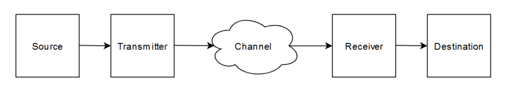
The main parts of interest for us here are the transmitter, channel, and receiver. For simplicity, let’s stick with a standard Nyquist rate system. Starting with the transmitter, we know it is going to send some data sequence. Mathematically, we write it as a column vector containing the data symbols. We will call this vector \( \bar{x}\).
When we deal with our transmitted data, we treat it as noiseless and shift the non-ideal aspects of the transmitter design (e.g. temperature induced noise in an IC) to the channel. The most common model we use for the channel is the Additive White Gaussian Noise (AWGN) model. For the uninitiated, AWGN is noise which is distributed according to a Gaussian distribution (AKA Normal distribution or the “Bell Curve” distribution) which is added onto the transmitted signal as it travels through the channel. The “white” part of the acronym indicates that the noise has 0 mean and this mean does not vary between transmissions. For our purposes, we will call the noise \( \bar{z}\). It too is a column vector.
Finally, the receiver will get our noise-corrupted signal. We express this observed signal \( \bar{y}\), and is evaluated by:
\( \bar{y} = \bar{x} + \bar{z}\)
Figure 2 shows an example of such a scenario through plotting.

Shifting our focus over to the FTN system, we are interested in characterizing the added complexity of ISI. While there are all kinds of approaches we could take, the one I’d like to take here is to observe an FTN data sequence for a simple pulse, come up with some ideas, and try to generalize our result. An important thing for us to keep in mind here is that we already have a model for the Nyquist Rate system, and it would be nice for us if we could keep it in a similar form.
A good choice for a simple pulse would be the rectangular pulse. When generating a sample transmission, I chose τ = 0.8 with a pulse width of 1s, and plotted three pulses. Figure 3 shows this.

We can notice from Figure 3 that, for each pulse, only a certain amount of the neighboring pulses overlap. An easy way (and what turns out to be the correct way) to characterize this overlap is to take the area of the overlap relative to a whole pulse. For the received symbol \( y_1\), ignoring noise, we can write it as:
\( y_1 = x_1 + 0.2x_2 \)
For \( y_2\):
\(y_2 = 0.2x_1 + x_2 + 0.2x_3\)
And for \( y_3 \)
\( y_3 = 0.2x_2 + x_3\)
If we wish to generalize these equations for some τ > 0.5, we will get:
\( y_1 = x_1 + (1-\tau)x_2\)
\( y_2 = (1-\tau)x_1 + x_2 + (1-\tau)x_3\)
\( y_3 = (1-\tau)x_2 + x_3\)
For those who are familiar with or just took linear algebra, this system of equations may set off a few alarm bells. To those who may not recognize it immediately, this system of equations is the result of a matrix multiplication operation. So, we can rewrite the system of equations (and consequently \( \bar{y}\) as a whole) to get:
\[\bar{y} = \begin{bmatrix}
1 & 1-\tau & 0 \\
1-\tau & 1 & 1-\tau \\
0 & 1-\tau & 1
\end{bmatrix} \begin{bmatrix} x_1 \\ x_2 \\ x_3 \end{bmatrix}
\]
Now, we have two key realizations. The first is that we can express ISI as the area of overlap between our symbols. The second is that we can convert this overlap into a system of equations which can be expressed as a matrix operation.
We call the matrix, H, containing information about the ISI the “ISI Matrix”. Let’s now write \( \bar{y}\) more generally as:
\( \bar{y} = H\bar{x}\)
While we certainly could show that the above equation holds for an arbitrary pulse (The ISI matrix will be different for different pulses), it isn’t an exercise that would glean any new information to us. We have made the key realizations that the area of overlap matters and that we can express our received signal as a matrix operation, which is all that is necessary for now. Finally, we can add noise back in to get a more realistic expression for the receiver’s observation.
\( \bar{y} = H\bar{x} + \bar{z}\)
So, we’ve gotten all of this written out. What do we do with it? How do we use it? Well, one important thing this equation tells us is that, when we are designing our system, we need to let the receiver and transmitter know what the ISI matrix is alongside the pulse we are using and τ. When we do this, we can use the ISI matrix to remove its effects at the receiver. We call this process equalization and is one of the tradeoffs I mentioned, though not by name, in the previous blog.
Goals for the Project
My goals for this project are straightforward, but also ambitious. Some of these terms may not be familiar now. We will address/introduce them as needed in future blogs. A basic list is below.
Present goals:
- BPSK Modulation System
- rRC pulse
- Coding Schemes to Implement (one or multiple of)
- Hamming74
- Viterbi Algorithm
- Reed-Solomon
- Reed-Muller
- Equalizers to Implement
- FDE-MMSE
- SSSgbKSE
Far Future Goals:
- Higher Order Modulation Schemes (e.g. QPSK)
- Capacity achieving codes (one or multiple of)
- Polar Code
- Turbo Code
- LDPC Code
- Transmission over Wireless Medium
Before I get hounded on this, I am aware of the vagueness of these goals, and they should be better defined. The reason for the vagueness is mostly because I am learning about the practical parts of this project as I go along. Of course, the general goal is to successfully implement the items in the list, and my metric for whether or not the implementation is successful will be based on the physical device’s agreement with simulations both at the physical and the datalink layer.
Acknowledgements
I would like to thank my friend Xander for proofreading this blog so its contents may be more easily accessible for a general audience. You can find his website at goodxander.wordpress.com.
I’d also like to thank my partner on this project Morrison for his aid in simulation and design work.
Leave a Reply